Introduction
In the following you find information which can help you to upgrade your Hacksculpt. Be warned, its a process that takes quite a lot of time and some electronics experience.
Upgrading the electronics gives you many opportunities, use the latest Slicer and Host software and run a decent firmware were the most important one for me. Secondly this allowed me to replace the extruder hot end with a better quality one, which would not have been possible with the original firmware as you would not be able to change settings such as E-steps.
After hacking the Freesculpt printer (which is just a relabeled Myriwell product), which was manufactured in the mid-2013, I must say that in some parts a very well designed product for a low price tag, then, when it comes to software, customization and failure rate is just very painful. This is also how I received the Myriwell: With broken electronics, and software which was a time travel experience with occasional smileys greeting me (“uploading file ^-^”).
Hacking the Microcontroller for custom firmware?
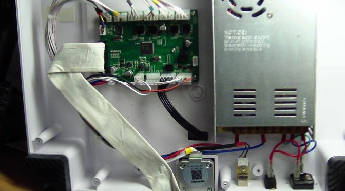
There is an JTAG port available on the main PCB which would possibly allow for reflashing a custom firmware, after figuring out all Pin definitions manually. However the uC itselfs is quite limited and could just about run a recent Reprap firmware without nice features such as display or SD card. Plus, if the board fails not clear how you can get replacement.
Internal Power supply:
24V, 15 A
Extruder Temperature sensor:
Type-K Thermocouple (read out by MAX6675)
Heated Bed:
Temperature sensor 15k NTC SMD (possibly Vishay NTCS0805E3…..T)
Heater cold resistance: 3.7 Ohms
Readouts are very good NTC with 15k and B=3700.
Electronics:
Custom controller board, custom SD/Pushkey board, Third-Party LCD Graphics display 12864G
ATmega64A (16 MHz, 64 kByte Flash,4 kB SRam)
Endstops:
5V Electrical Endstops, Normally Open (1-Open, 0-Closed)
General color coding:
Black – x
Green – Y
Yellow – Z
No Mark – Extruder
Belt /Pulleys (X/Y)
TB2 (2mm Pitch)
17-teeth
Leadscrew driven system (Z)
Leadscrew with multiround (4-rounds) with a pitch of 8mm/turn.
Stepper motors:
All 200 steps / revolution.
Stepper drivers:
A4988
Internal Harness Color Coding
Does not exist, the wire marks for all wires are arbitrary.
Maximum Moving distance:
X=290mm
Y=160mm
Z=150mm
Hacking a Freesculpt / Myriwell 3D Printer
Endstops: 1-GND, 2-VCC, 3-SIG (default as Sanguinololu, Different than RAMPS)
Motor Coding: 2B 2A 1A 1B (default as for Reprap)
Printer Settings: Calculation
These settings work very good for XYZ axis.
Result Resolution Teeth Step angle Stepping Belt
94.12 steps/mm
10.624999999999998micron 17 1.8° 1/16th 2mm
Result Leadscrew pitch Step angle Stepping Gear ratio
400.00 steps/mm
8 1.8° 1/16th 1 : 1
Printer settings: Complete package (configuration.h, EEPROM, Printer size setting)
I have prepared a complete download of all my settings to help you reverse engineer. The configuration.h does not have the most recent settings such as extruder steps (which should be different for you) as well as print bed size and some settings.
http://space.planetsofa.de/files/freesculpt_settings_2016_04_10.zip